 English
 русский
Qisheng
Qisheng
Qisheng
Qisheng
Qisheng
Qisheng
Qisheng
Qisheng
Qisheng
Table of Contents
- 1 The Three Tool Specs That Set Your Target
- 2 Flow Matching: Read the Rating as a Band, Not a Point
- 3 Pressure Matching: Set the Relief Above the Tool, Not Above the Pump
- 4 One Formula and Six Power Classes
- 5 Circuit Type Decides Whether the Match Holds Under Load
- 6 A Six-Step Field Matching Workflow
- 7 Mismatch Symptoms and What They Actually Mean
- 8 Practical Questions From the Field
Two hydraulic breakers leave the depot behind the same 35 HP power pack. One hammers at its rated blow rate for a full shift. The other stalls at roughly 1,100 blows per minute, runs hot, and darkens the return filter inside three hours. The breaker is the same model, and so is the engine. What differs is whether flow and pressure were matched as a pair or copied from a single line on a spec plate.
Matching a hydraulic power unit (HPU) to a hydraulic tool means selecting pump displacement, prime-mover size and a relief setting that hold the tool inside its rated flow band at its rated working pressure, with enough headroom for the circuit's own losses. Two of the three correct still produces an underperforming machine.
The Three Tool Specs That Set Your Target
A hydraulic tool states its power unit requirement with exactly three numbers, and all three bind the selection: rated flow, working pressure and maximum allowable pressure.
- Rated flow (L/min or gpm). The volume the tool needs to reach its rated cycle rate. A breaker rated at 60 L/min still fires at 45 L/min, but blow rate and impact energy per stroke both fall away.
- Working pressure (bar or psi). The pressure at which the tool produces its rated output. This is the figure the circuit is designed around.
- Maximum allowable pressure (bar or psi). The ceiling above which seals, accumulators and the tool body are at risk. This is the figure the relief valve protects.
When a datasheet lists one flow figure with no band, treat it as the middle of the band and ask the supplier for the tolerance. Tools with a tight band of plus or minus 10 percent are usually the ones carrying an internal accumulator, because the accumulator needs a predictable recharge window between cycles.
A recurring sizing error is selecting a power unit whose maximum pressure equals the tool's maximum pressure. Working pressure and maximum pressure are separate figures, and the space between them is the relief margin that keeps the tool alive.
Flow Matching: Read the Rating as a Band, Not a Point
Hydraulic tools are rated across a flow band of roughly plus or minus 10 to 15 percent around a nominal value, and the penalties for missing that band are not symmetrical.
Run below the band and the tool still works: it cycles slower, and for impact tools the energy per blow drops as well, because the accumulator cannot recharge fully between strikes. Run above the band and the surplus flow has nowhere to go except across the relief valve, where it converts directly into heat. A 35 HP pack pushing 75 L/min into a tool that accepts 50 L/min turns roughly 8 kW of engine output into oil temperature.
Nominal drive-flow demand by tool class, litres per minute
Breaker, 30 to 60 kg
30
Breaker, 100 to 150 kg
55
Breaker, 1,000 to 1,500 kg
130
Hydraulic cut-off saw
32
Hydraulic core drill
35
Submersible slurry pump, 75 mm
75
Aim the pump's usable flow at the middle of the tool's band rather than the top of it. The midpoint leaves room for the flow loss that appears as oil warms and viscosity falls. When one power unit drives several tools on a manifold, size for the highest-flow tool and fit a flow divider if two tools ever run at the same time.
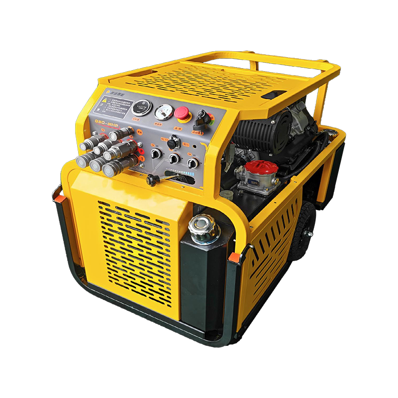
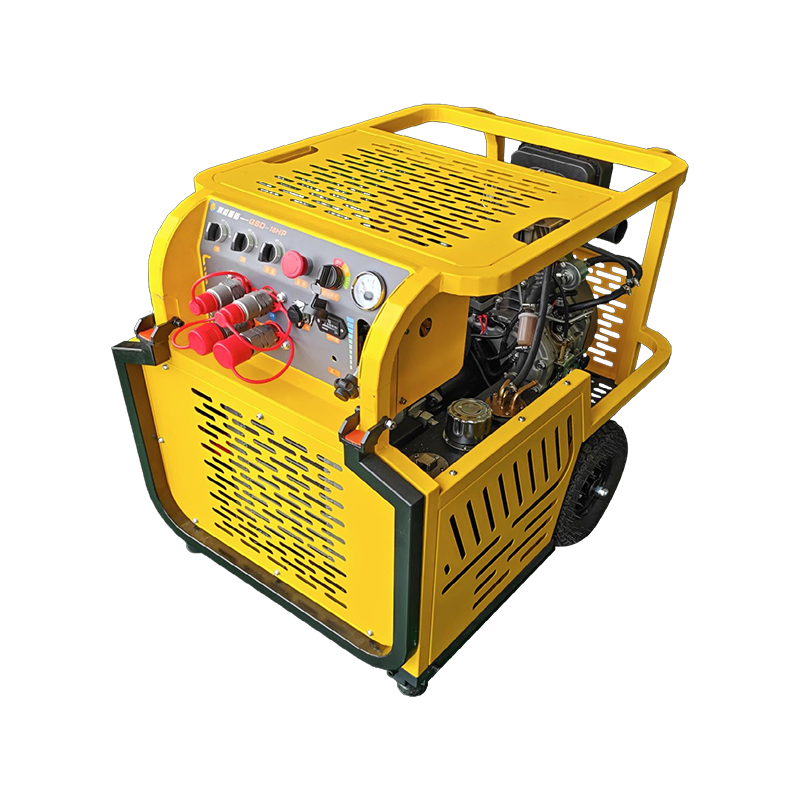
 18HP DualOption Portable Hydraulic Power UnitA twin-cylinder, dual-circuit mobile unit with 155 bar pressure and 20/40 Lpm flow, suited to matching tool flow and relief settings.View Product →
A breaker running 20 percent below its rated flow does not simply cycle 20 percent slower. Impact energy per blow falls too, because the accumulator never reaches full charge between strikes.
Pressure Matching: Set the Relief Above the Tool, Not Above the Pump
Set the main relief valve 10 to 15 percent above the tool's maximum working pressure, and never above the lowest-rated component anywhere in the circuit.
The pressure you set is a system pressure, not a pump pressure. Between the pump outlet and the tool inlet sit a directional valve, quick couplers, hoses and a return filter, and each one claims its own drop. The governing general-safety standard for hydraulic systems, ISO 4413, places pressure limitation at the circuit level for exactly this reason: the pump cannot see what the tool inlet is doing.
10 to 15%Relief margin above the tool's maximum working pressure
1,714Divisor converting gpm x psi into hydraulic horsepower
600Divisor converting L/min x bar into kilowatts
Hose class frequently sets the real ceiling. Two-wire braided hose to SAE 100R2 carries about twice the working pressure of single-wire braid to SAE 100R1 in the same bore, so a circuit that is fine on 100R2 becomes marginal the moment a 100R1 assembly is swapped in during a field repair.
Set the relief once, then verify it with a gauge at the tool inlet while the tool is under load. A gauge at the pump outlet will read 10 to 20 bar higher than the tool sees, which is the gap that hides an over-pressure fault until a seal fails.
One Formula and Six Power Classes
Required hydraulic power equals flow multiplied by pressure, divided by 1,714 in imperial units or by 600 in metric units.
HP = (gpm x psi) / 1,714
kW = (L/min x bar) / 600
Both results describe hydraulic output at the pump outlet. Add a 15 percent reserve for prime-mover and volumetric losses, because a gasoline engine driving a gear pump returns 80 to 88 percent of its rated output at the outlet once oil temperature stabilises.
| Power class | Nominal pressure | Usable flow | Typical tool match |
| 13 HP gasoline | 175 bar | 28 L/min | 30 to 60 kg breaker, cut-off saw |
| 18 HP dual-option | 175 bar | 39 L/min | 100 to 150 kg breaker, core drill |
| 35 HP high-flow | 175 bar | 75 L/min | 600 to 900 kg breaker, 75 mm slurry pump |
| 80 HP open-frame | 200 bar | 150 L/min | 1,000 to 1,200 kg breaker, 8 inch axial pump |
| 130 HP enclosed | 210 bar | 235 L/min | 1,400 kg breaker, 12 inch flood pump |
| 300 HP enclosed | 250 bar | 455 L/min | Multi-tool manifolds, high-flow slurry pumps |
For breaker duty specifically, a hydraulic power pack for hydraulic breakers is sized from the hammer's flow band first and its pressure second, because the relief setting rarely needs to exceed 180 bar on hammers below 900 kg.
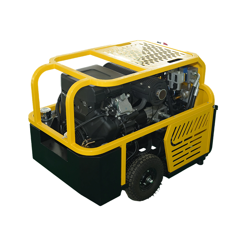 35HP HighFlow Portable Hydraulic Power UnitA heavy-duty triple-circuit pack with 175 bar and 40/80 Lpm outputs, relevant when sizing breaker duty by flow before pressure.View Product →
Circuit Type Decides Whether the Match Holds Under Load
An open-center power unit feeding a closed-center tool will deadhead the pump within seconds, and the two architectures are not interchangeable without a conversion valve.
Open center
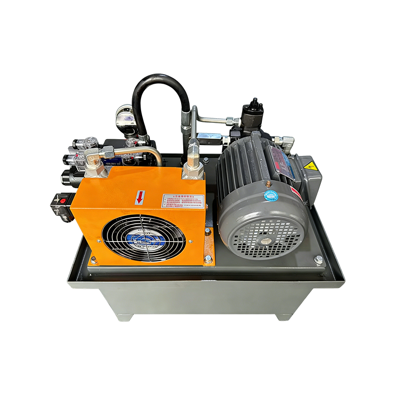
A fixed-displacement pump circulates oil through the valve back to tank at low pressure while the tool is idle, so the circuit runs cool on standby. Pressure rises only when the spool closes. Best suited to single-tool, intermittent duty such as breakers, saws and drills.
Closed center with load sensing
The pump holds pressure with near-zero flow when the valve is centered, and a compensator matches displacement to demand. Standby heat is minimal, multi-tool manifolds behave predictably, and the compensator is normally set 15 to 25 bar above the highest load in the circuit.
Check the compensator margin before adding a second tool. The highest-pressure function in a shared circuit sets the pump's standby pressure, and a low-pressure function added downstream will throttle and heat unless it has its own pressure-reducing valve.
A Six-Step Field Matching Workflow
Working through these six steps in order takes about twenty minutes with a datasheet and a calculator, and it prevents every mismatch listed later in this article.
- Record the tool's rated flow band, working pressure and maximum allowable pressure from its plate, not from a catalogue summary.
- Add the circuit losses: 3 to 5 bar for a 10 m pressure hose at rated flow, plus 2 to 4 bar across a return filter.
- Compute required power with the 1,714 or 600 divisor, then add a 15 percent reserve.
- Choose the power class whose usable flow lands near the middle of the tool's flow band.
- Set the main relief 10 to 15 percent above the tool's maximum working pressure, then confirm it sits below the lowest-rated component in the circuit.
- Size the reservoir for 2 to 3 times pump flow per minute on breaker duty, and verify oil temperature settles below 60 degrees C after one hour of continuous work.
Buyers who would rather compare than calculate can shortcut steps three and four by checking documented portable hydraulic power units for hydraulic tools against the tool band, since the flow, pressure and relief data for a matched package are already stated.
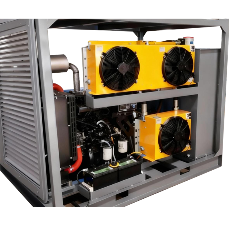 130HP Large-Scale Hydraulic Power UnitA high-flow, customisable unit for shipbuilding, metallurgy, mining and construction, positioned for comparing matched packages against tool requirements.View Product →
Mismatch Symptoms and What They Actually Mean
Five symptoms account for nearly every mismatch reported in the field, and each one points to a specific correction rather than a general "wrong unit" verdict.
| Symptom | Likely mismatch | Correction |
| Blow rate below rating, no heat problem | Flow below the tool's band | Step up one pump displacement or one engine class |
| Oil above 70 degrees C within an hour | Surplus flow dumped across the relief | Reduce displacement or fit a flow divider |
| Hammer stalls mid-stroke | Relief set below working pressure | Raise relief to 10 to 15 percent above tool maximum |
| Pump whines continuously under load | Suction starvation or wrong viscosity grade | Resize suction line, confirm ISO VG 46 oil |
| Couplers hot to the touch | Restriction at the tool inlet | Replace worn ISO 16028 flush-face couplers |
Practical Questions From the Field
How do I convert a tool rated at 12 gpm and 2,000 psi into a power unit size?
Multiply flow by pressure and divide by 1,714: (12 x 2,000) / 1,714 = 14.0 hydraulic horsepower. Add the 15 percent reserve and the requirement becomes 16.1 HP, which places the tool in the 18 HP class. In metric, 45 L/min at 140 bar gives (45 x 140) / 600 = 10.5 kW, and adding reserve puts it at 12.1 kW.
Can a 35 HP power pack run a 1,000 kg class breaker?
No. A 1,000 kg class breaker draws 100 to 160 L/min at 160 to 180 bar, which needs 45 to 60 kW of hydraulic output, equivalent to roughly 60 to 80 HP at the pump. A 35 HP unit delivers about 75 L/min at 175 bar, so the hammer fires below its rated blow rate while oil temperature climbs past the safe band.
Which oil viscosity and cleanliness grade should a matched circuit hold?
ISO VG 46 mineral oil covers ambient temperatures from roughly 10 to 40 degrees C, and ISO VG 32 is the better choice below 10 degrees C. Hold cleanliness at ISO 4406 code 18/16/13 or better for tools with close-tolerance valves, because a single particle larger than the valve clearance will score a spool and create an internal leak that mimics a flow shortfall.