
 English
 русский



Hydraulic Pump for Flood Rescue
Hydraulically driven pump engineered for rapid floodwater removal during emergency response, rescue operations, and disaster recovery where electrical infrastructure is compromised
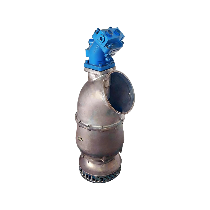
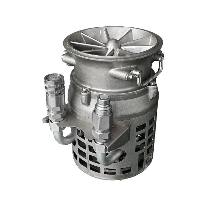
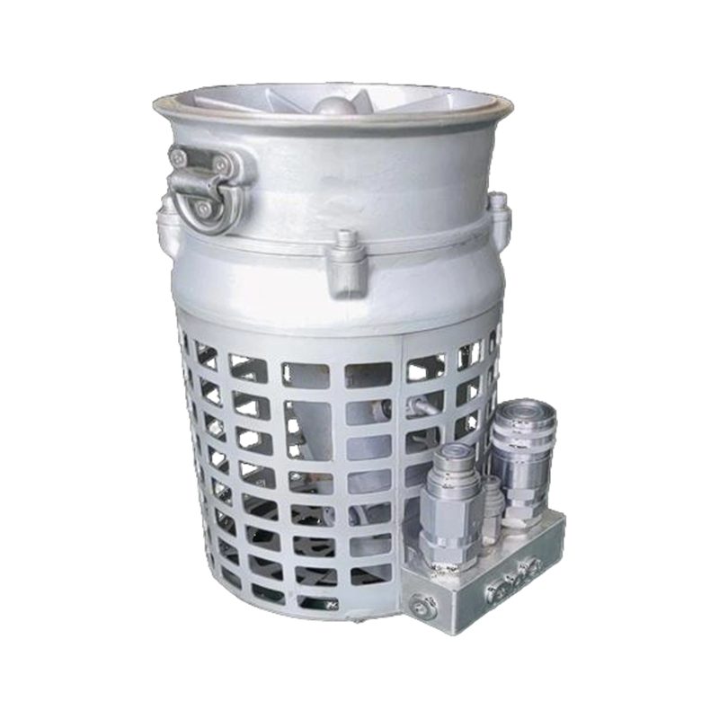
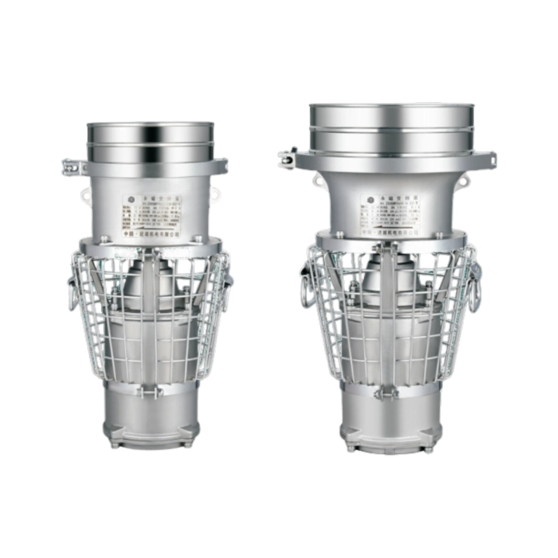
The Hydraulic Pump for Flood Rescue is a hydraulically driven submersible pump designed for emergency water removal in flood and disaster response operations. The pump operates from an external hydraulic power unit, with no electrical motor or cable in the submerged assembly, allowing deployment in flooded areas where electrical infrastructure is damaged or unsafe. The unit delivers up to 320 m³/h at heads up to 30 meters, with a 45 mm solids passage to handle floodwater carrying debris, sand, and silt. The pump body is cast iron with a replaceable wear plate, and the impeller is semi-open cast iron for debris tolerance. The compact submerged profile allows lowering through manholes and into confined spaces, and the hydraulic couplers permit rapid connection to a rescue vehicle's hydraulic circuit. The unit is suited to procurement by fire services, civil defense agencies, municipal emergency departments, and rescue equipment distributors requiring a pump that can be deployed without electrical setup.
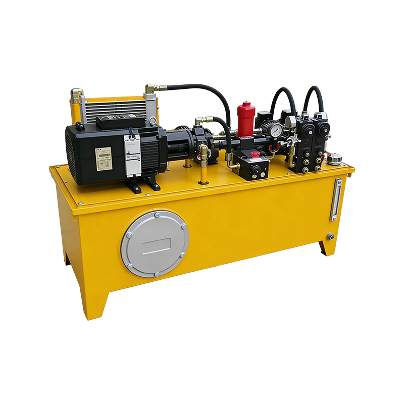
Yes, provided the vehicle's hydraulic flow and pressure are matched to the pump's hydraulic motor specification. Rescue vehicles typically supply hydraulic flow for rescue tools, and the pump's motor displacement can be selected to operate within that flow range. Agencies should provide the vehicle model, flow in liters per minute, maximum pressure, and relief valve setting at inquiry stage. The coupler type must also be confirmed so the pump connects directly to the vehicle circuit.
The semi-open impeller passes solids up to 45 mm in diameter, covering sand, gravel, small stones, vegetation, and urban debris commonly present in first-phase floodwater. For water containing large objects or heavy fibrous material, a strainer with larger openings or a trash pump should be specified. Buyers should confirm the expected debris profile so the impeller and strainer configuration can be matched to the response environment.
Deployment time depends mainly on access to the water and the coupler arrangement. With matched quick couplers, connection to the hydraulic circuit takes under two minutes. Lowering the pump into position and connecting the discharge hose typically adds two to three minutes. Total time from arrival to pumping is generally under five minutes with a trained crew, provided the hydraulic circuit and discharge route are accessible.
The hydraulic motor and shaft bearings are lubricated by the hydraulic circuit rather than the pumped water, so the pump can run dry without immediate bearing failure. However, the mechanical seal relies on water for cooling, and extended dry running accelerates seal face wear. In flood response, where water level may drop as pumping progresses, operators should monitor the water level and stop the pump when the inlet is exposed, or use a level control arrangement on the power unit circuit.
After each deployment, flush the pump casing and impeller with clean water to remove sediment and debris. Inspect the hydraulic couplers for damage or contamination, and check the hoses for abrasion. Verify the impeller and wear plate condition, and replace worn parts as needed. For units in standby, run the pump briefly each month to confirm free rotation and coupler function, and keep a spare wear part kit with the response unit.
A complete inquiry should include: required discharge flow in cubic meters per hour; required head in meters; rescue vehicle hydraulic flow in liters per minute and maximum pressure in bar; relief valve setting; existing coupler type and standard; required discharge outlet size and hose length; expected submersion depth; and the expected debris content of the floodwater. For fleet procurement, indicate the number of response units and whether the specification must remain fixed across repeat orders.