
Construction Site Equipment HPCD Series / Dewatering File
Available for Project Specification
Hydraulic Dewatering Series

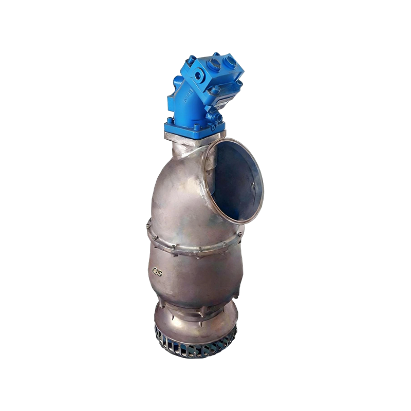
Hydraulic Pump for Construction Dewatering

Hydraulically driven pump for excavation dewatering, foundation pit drainage, and construction water removal where electrical equipment in wet conditions is restricted

Site Duty Excavation and pit dewatering
Excavation Dewatering Section
Ground Level
Excavation Pit
Hydraulic Hose
300 m³/h Max Discharge
45 m Max Head
40 mm Solid Passage
IP68 Submersion Rating
Product Introduction

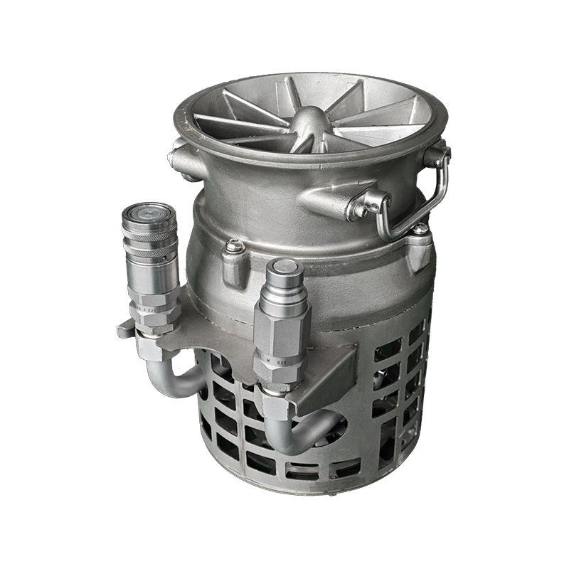
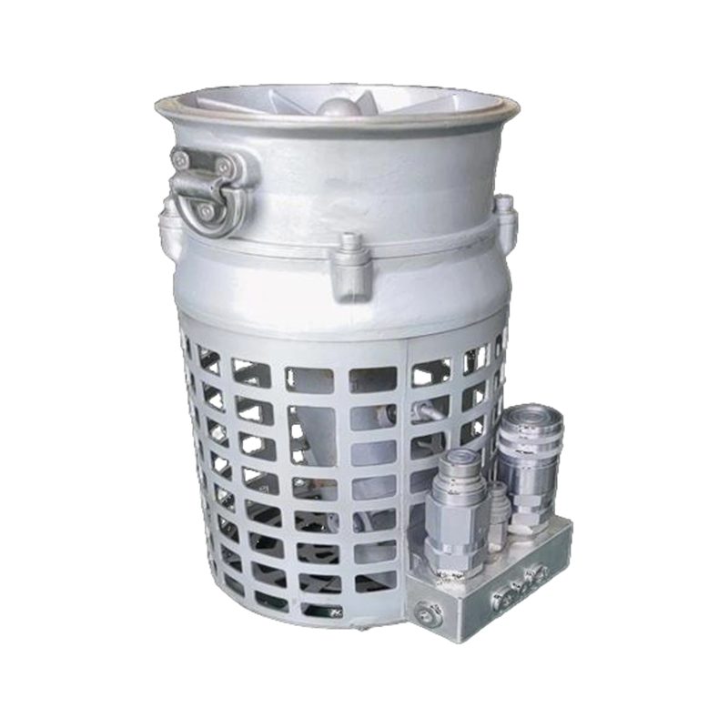
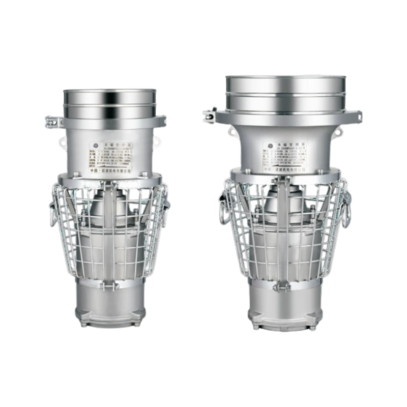
The Hydraulic Pump for Construction Dewatering is a hydraulically driven submersible pump designed for water removal from excavations, foundation pits, trenches, and construction sumps. The pump operates from an external hydraulic power unit, with no electrical motor or cable in the submerged assembly, which suits construction sites where wet conditions, temporary power arrangements, and confined pit access make electric submersibles difficult to deploy and maintain. The unit delivers up to 300 m³/h at heads up to 45 meters, sufficient to lift water from deep excavations to surface discharge points. The 40 mm solids passage handles water carrying soil, sand, and small aggregate from excavation operations. The pump body is cast iron with a replaceable wear plate, and the impeller is semi-open cast iron. The compact submerged profile allows lowering into narrow pits and trenches, and the hydraulic couplers permit connection to a site power unit or excavator hydraulic circuit. The unit is suited to procurement by general contractors, groundworks specialists, and plant hire companies.

Technical Parameters
Pump type Hydraulically driven centrifugal, submersible
Maximum discharge 300 m³/h
Maximum head 45 m
Solid passage 40 mm
Discharge outlet 100 mm (4 inch) or 150 mm (6 inch) flange
Submersion rating IP68, continuous submersion
Maximum submersion depth Up to 22 m, model dependent
Impeller material Cast iron, semi-open design
Casing material Cast iron with replaceable wear plate
Hydraulic connection Flat-face quick couplers, hose length to be specified
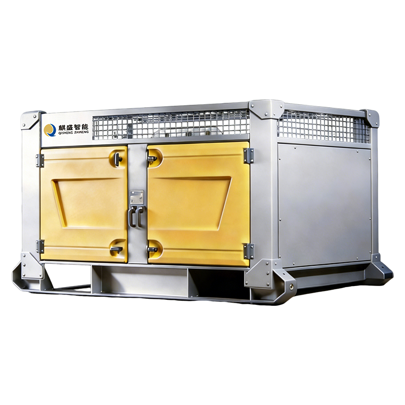
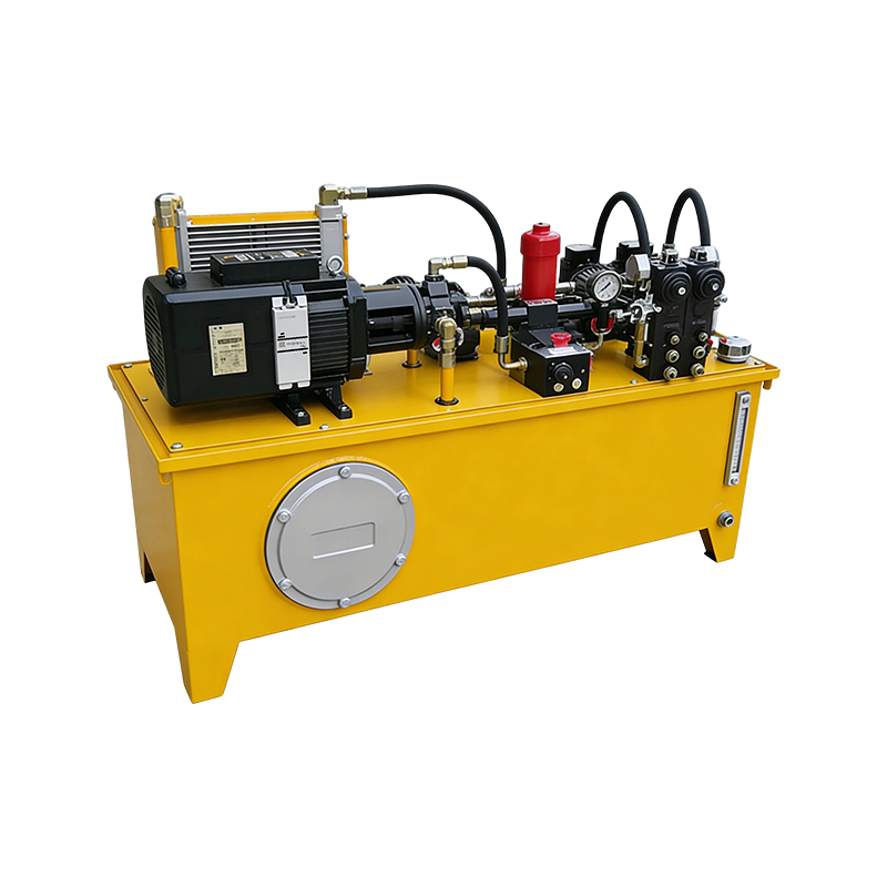
Hydraulic supply External power pack or excavator circuit; flow and pressure to be confirmed
Dry weight Approximately 52 kg for 100 mm model, to be confirmed
Core Advantages
01
No Electrical Equipment in the Pit The pump contains no electrical motor, cable, or junction box in the submerged assembly. Hydraulic power is supplied through hoses from a power unit positioned at ground level, which simplifies electrical safety management in excavation pits where temporary power and wet conditions coexist.
02
Excavator Hydraulic Circuit Compatibility The pump can operate from an excavator's hydraulic circuit, avoiding the need to transport and set up a separate power unit. Coupler type and motor displacement are matched to the excavator circuit specification at order stage.
03
Soil and Aggregate Tolerance The 40 mm solids passage accommodates soil particles, sand, and small aggregate carried into the pit by groundwater and surface runoff. The replaceable wear plate allows the impeller clearance to be restored as abrasive wear occurs.
04
Compact Profile for Narrow Trenches Without an integral electric motor housing, the pump body is shorter than an equivalent electric submersible, allowing lowering into narrow trenches and confined pit corners where larger units cannot be positioned.
05
Output Adjustable at the Power Unit Flow and head are regulated by varying hydraulic oil supply rather than by electrical speed control. This allows the pump output to be matched to changing groundwater inflow rates and discharge line lengths as the excavation progresses.
06
Shared Site Hydraulic Infrastructure A single power unit or excavator circuit can drive multiple pump heads positioned at different pits along the site. For contractors already operating hydraulic equipment, dewatering pumps can be added without new electrical installations.
Working Condition Matrix
Foundation Pit Dewatering Continuous removal of groundwater and rainwater from foundation excavations during earthworks and concrete operations. The pump is lowered into the pit sump and connected to a ground-level power unit.
Trench and Pipeline Drainage Dewatering of service trenches and pipeline excavations where the pump must fit within narrow working widths. The compact body allows positioning between trench walls.
Basement and Sublevel Construction Removal of accumulated water from below-grade construction areas and lift pits. The hydraulic drive avoids cable routing through wet structural openings.
Groundwater Control During Piling Dewatering of boreholes, piling platforms, and surrounding excavations where water ingress affects drilling and concrete placement.
Site Runoff and Surface Water Removal Removal of rainwater and surface runoff from site compounds, haul roads, and material storage areas. The 40 mm solids passage handles water carrying soil and aggregate particles.
Plant Hire and Contractor Fleet Deployment Plant hire companies and groundworks contractors procure hydraulic pump heads to operate with existing excavators and power units across multiple sites, avoiding separate electric pump variants for each project.
Manufacturing and Supply Capabilities
Casting and machining Casing and impeller produced through casting with subsequent machining of sealing faces, wear plate seat, and bearing bores. Casting source and machining tolerance capability to be confirmed with the factory.
Hydraulic motor integration Hydraulic motor assembled into the sealed pump housing with shaft coupling. Motor displacement selected according to the excavator or power unit flow, pressure, and relief valve setting.
Coupler compatibility Coupler type matched to the contractor's existing excavator circuit connections. Common construction equipment coupler standards can be accommodated; specific coupler specification to be confirmed at order stage.
Wear part supply Replaceable wear plates, impellers, and mechanical seal cartridges supplied as service parts. Wear part inventory levels and replenishment lead times to be confirmed.
Custom configuration Discharge outlet size, hydraulic motor specification, hose length, and coupler type can be adjusted to match existing excavator circuits and pit access dimensions. Minimum order quantity for custom configurations to be confirmed.
Batch production Production scheduling accommodates repeat orders for contractor fleets and plant hire stock. Batch sizes and production cycle times to be confirmed against current factory capacity.
Quality inspection Inspection covers hydraulic circuit pressure testing, seal integrity verification, submersion rating check, impeller clearance measurement, and free rotation check of the shaft assembly. Test records and third-party inspection arrangements to be confirmed.
Export packaging Pump heads packed in wooden cases with hydraulic ports capped and hoses coiled separately. Packaging configuration for sea freight and contractor branding requirements to be confirmed.
B2B Buyer Considerations
Excavator or Power Unit Matching The pump's hydraulic motor must be matched to the flow and pressure available from the excavator or power unit. Contractors should provide the machine model, hydraulic flow in liters per minute, maximum pressure, and relief valve setting. Coupler type must also be confirmed to ensure direct connection without adapters.
Pit Depth and Access Dimensions The pump must fit within the excavation footprint and reach the pit sump. Contractors should provide the pit depth, working width, and the vertical lift required from the sump floor to the discharge point. This determines the pump model, submersion depth rating, and discharge head requirement.
Wear Part Planning for Soil-Laden Water Construction dewatering water often carries soil and sand that accelerate wear. Contractors should confirm the supplier's wear plate and impeller availability, and hold a spare wear part kit per pump head for project continuity. Replacement intervals depend on the abrasive content of the water and the duty hours.
Hose Routing Across Site Access Routes Hydraulic hoses run from the pump in the pit to the power unit or excavator at ground level, often crossing site access routes and working areas. Contractors should plan hose routing with protection against plant traffic and material handling, and confirm the required hose length at order stage.
Documentation for Project Method Statements Construction projects often require technical datasheets, pressure test certificates, and material declarations for method statements and site safety documentation. Availability of these documents, and the supplier's ability to provide them consistently across project phases, should be confirmed during the inquiry.
Frequently Asked Questions

Yes, provided the excavator's hydraulic flow and pressure are matched to the pump's hydraulic motor specification. Excavators typically supply hydraulic flow for attachments, and the pump's motor displacement can be selected to operate within that flow range. Contractors should provide the excavator model, flow in liters per minute, maximum pressure, and relief valve setting at inquiry stage, along with the coupler type used on the machine circuit.

The semi-open impeller passes solids up to 40 mm in diameter, covering soil particles, sand, small stones, and aggregate fragments carried into the pit. For water containing larger objects or heavy fibrous material, a strainer with larger openings or a trash pump should be specified. Contractors should confirm the expected solids profile so the impeller and strainer configuration can be matched to the site conditions.

The required head is the vertical distance from the pit sump water level to the discharge point, plus friction losses in the discharge hose or pipe. For a 25-meter vertical lift with 70 meters of discharge hose, the total head requirement is typically 30 to 35 meters. The pump's maximum head of 45 meters provides margin for friction losses and discharge pressure. Contractors should provide the vertical lift and discharge line length so the required head can be confirmed.

Matching requires three inputs from the power unit: hydraulic flow in liters per minute, maximum pressure in bar, and relief valve setting. The pump's hydraulic motor displacement is selected so that the available flow produces the required impeller speed. Providing these figures along with the required discharge head, flow, and vertical lift allows the supplier to specify the correct motor. If the power unit model is known but the flow figures are not, the supplier can typically match the motor from the model number.

The pump can be operated with a level control valve or float switch on the power unit circuit to start and stop automatically based on water level. However, unattended operation in an excavation pit requires consideration of hose security, access control, and site safety procedures. Contractors should confirm the site arrangements before planning unattended operation, and confirm whether the power unit supports automatic start-stop control.

After each dewatering cycle, flush the pump casing and impeller with clean water to remove soil and sediment. Inspect the hydraulic couplers and hoses for abrasion or damage. Check the impeller and wear plate condition, and replace worn parts as needed. Verify that the pump rotates freely. For units in standby, run the pump briefly each week to confirm operation and prevent seal sticking.

A complete inquiry should include: required discharge flow in cubic meters per hour; vertical lift from pit sump to discharge point in meters; discharge line length and diameter; excavator or power unit hydraulic flow in liters per minute and maximum pressure in bar; relief valve setting; coupler type; pit depth and working width; expected solids content of the water; and the number of pits to be served. For contractor fleet procurement, indicate the estimated annual quantity and whether the specification must remain fixed across repeat orders.

Est. 2014 high-end hydraulic
Wuhu Qisheng
Intelligent Equipment

Professional China designer & custom manufacturer, suppliers of Hydraulic Pump for Construction Dewatering for emergency, rescue, agricultural water conservancy, and environmental protection.

Deeply engaged

We keep up with industry trends and empower efficient operations with professional strength.

Senior R&D engineers Technical pain point solutions Efficient production system Rapid market response
200+
projects delivered
98%
on‑time delivery
emergency rescue environmental agricultural water
Engineering excellence

Deeply engaged in the hydraulic equipment industry, we keep up with trends and empower efficient operations with professional strength. Our core competitiveness lies in strong technological and production capabilities.

We have a team of senior R&D engineers with rich practical experience. Accurately grasping technical pain points and demand directions, we provide solid support for product innovation.

Our engineers work closely with clients to translate operational challenges into precise technical specifications, ensuring every solution is fit for purpose.

Production & agility

Equipped with an efficient production system, we realize seamless connection between R&D and production, quickly respond to market changes, meet diverse customer needs, and ensure delivery efficiency and product stability.

Rapid prototyping & testing
Flexible manufacturing capacity
Just-in-time inventory management
End-to-end quality control
Lean production workflows
Automated assembly lines
24/7technical support
100+custom solutions
48hrapid response
99%quality pass rate
Product portfolio

Our products cover multiple categories including hydraulic power stations, slurry pumps, integrated and portable water pump equipment, and hydraulic breakers — for drainage, dredging, forest fire fighting, cutting, drilling, and sand suction.

With comprehensive functions, our products can be widely used in various scenarios such as drainage, dredging, forest fire fighting, cutting, drilling, and sand suction, adapting to the actual operation needs of core fields such as emergency rescue and environmental construction.

Non‑electric drive

Safe operation in hazardous environments, high lift, strong wear resistance, easy mobility — hardcore equipment under complex working conditions.

Customized R&D

Full‑process tailored solutions to solve your personalized operation problems. We design exclusive hydraulic equipment for your specific needs.

200+
projects delivered
98%
on‑time delivery
24/7
technical support
100+
custom solutions
Development philosophy
“Promoting the development of emergency rescue hydraulic equipment and leading the technological innovation of the industry.”

We adhere to the original intention of quality, focus on customers' core demands, and are committed to providing high‑quality, highly competitive products, customized solutions and comprehensive services.

Strategic partner
Reliable · professional · sustainable
Core fields
Emergency rescue Agricultural water Environmental protection Forest fire fighting
R&D driven custom solutions quality first

Get in touch